F4VSG’s OSCAR 100 WB DATV TX setup
As mentioned before on this site, it is difficult for me to make QSO’s on VHF ++ frequencies due to surrounding hills and mountainous area’s around me.
So the new launched ESHAIL / OSCAR-100 was an new challenge for me!!
In the first period after the OSCAR-100 was available for HAM’s I tested first with a horizontal polarized yagi under an angle of approx. 30 degrees. I then used only 6 Watt RF for the SSB input part of the transponder.
Unbelievable that the satellite at that great distance from earth could receive that relative small signal from me.
Some days later I made a proper circular feed (tnx Remco PA3FYM)
First only testing with SSB, I used 15 meter Rosen 400 cable, so over 3 dB TX loss in the cable.
After that I put the 6 Watt PA at 5 meter (cable) distance of the dish-feed. Much better now.
Also I used about 30 Watt RF for DATV.
Now I use 10 meter CELLFLEX ½ coax with only approx.. 1,5 dB loss so much better.
With my RF power with DATV Express I finally could make a DATV picture, but needed more power to get a better stable picture.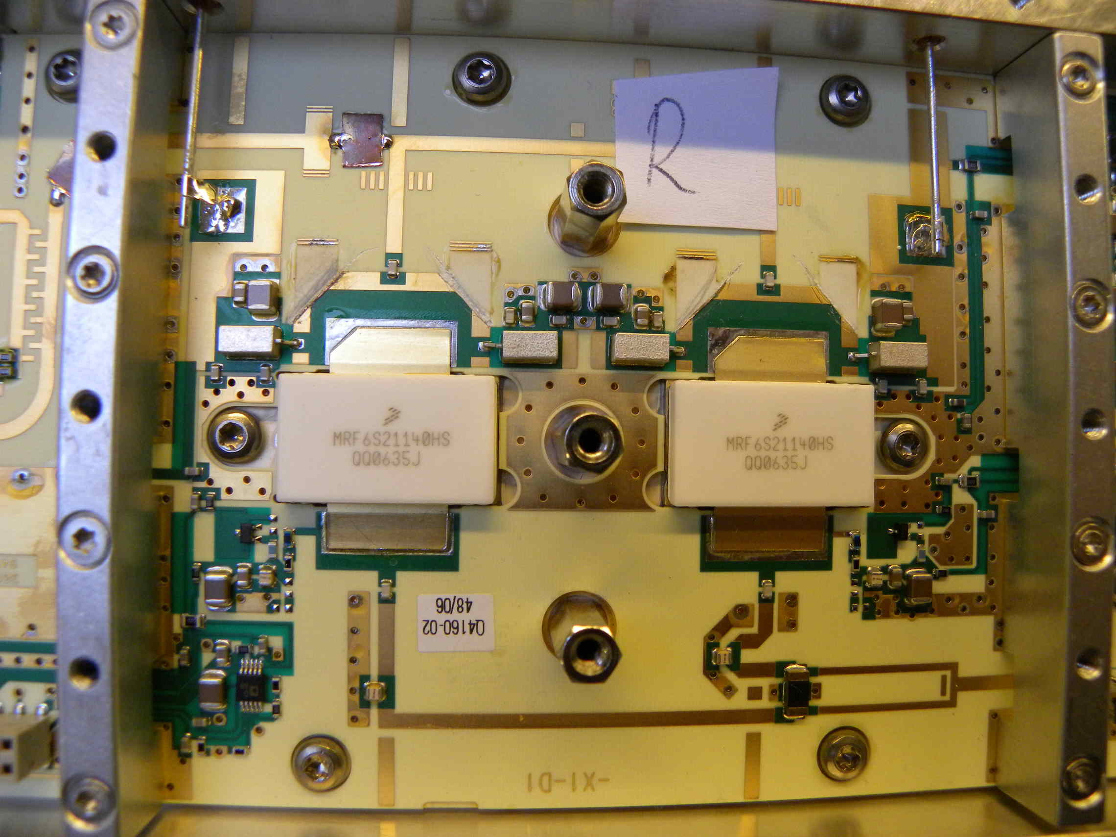
Siemens PA..
In the 2300 MHz area no problem to get over 100 Watt, but at 2408 MHz almost no power output.
The internally matched PA fets do not allow frequencies that high.
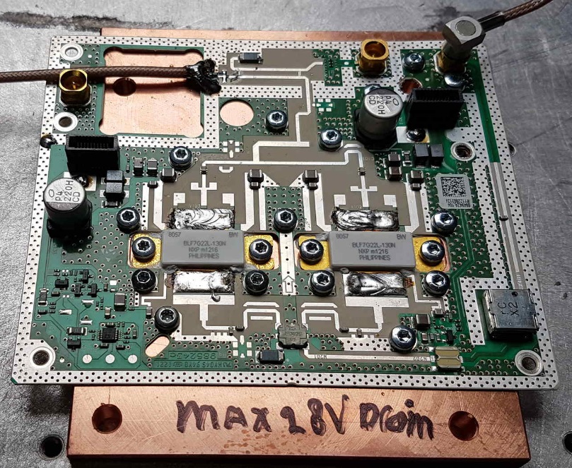
A new approach, with a recent GSM PA. Also here no great results.
may-june 2019 activities:
Then I found the Ampleon website with nice Powerfets for the 2400-2500 MHz frequency range.
Some of my HAM-friends also like to have proper RF power for their DATV transmissions. I promised to build some amplifiers for them, but first a proper design has to be build and tested properly before building a number of PA’s for 2400 MHz. So first I ordered a Ampleon module to make initial tests..
A small PCB with mounted single fet, RF-input and RF-output. Furthermore there are connections for gate voltage and drain power connections. 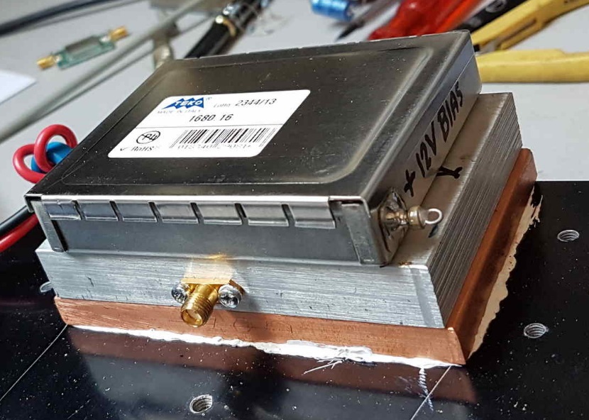
I did not use the temperature measurement output.
A simple setup was used for the bias current, A 7805 voltage regulator, diode protected, and a simple to adjust resistive control.
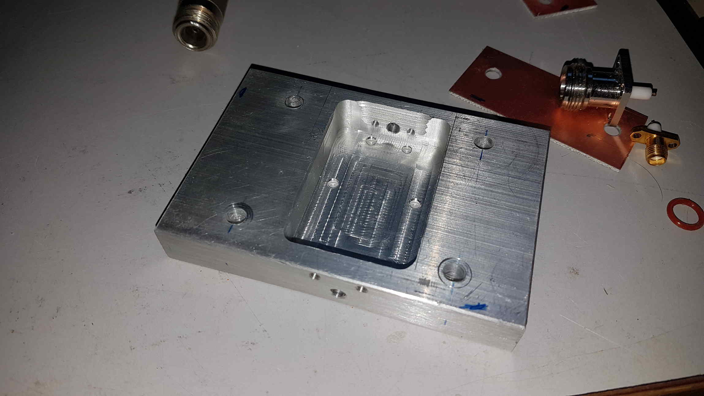
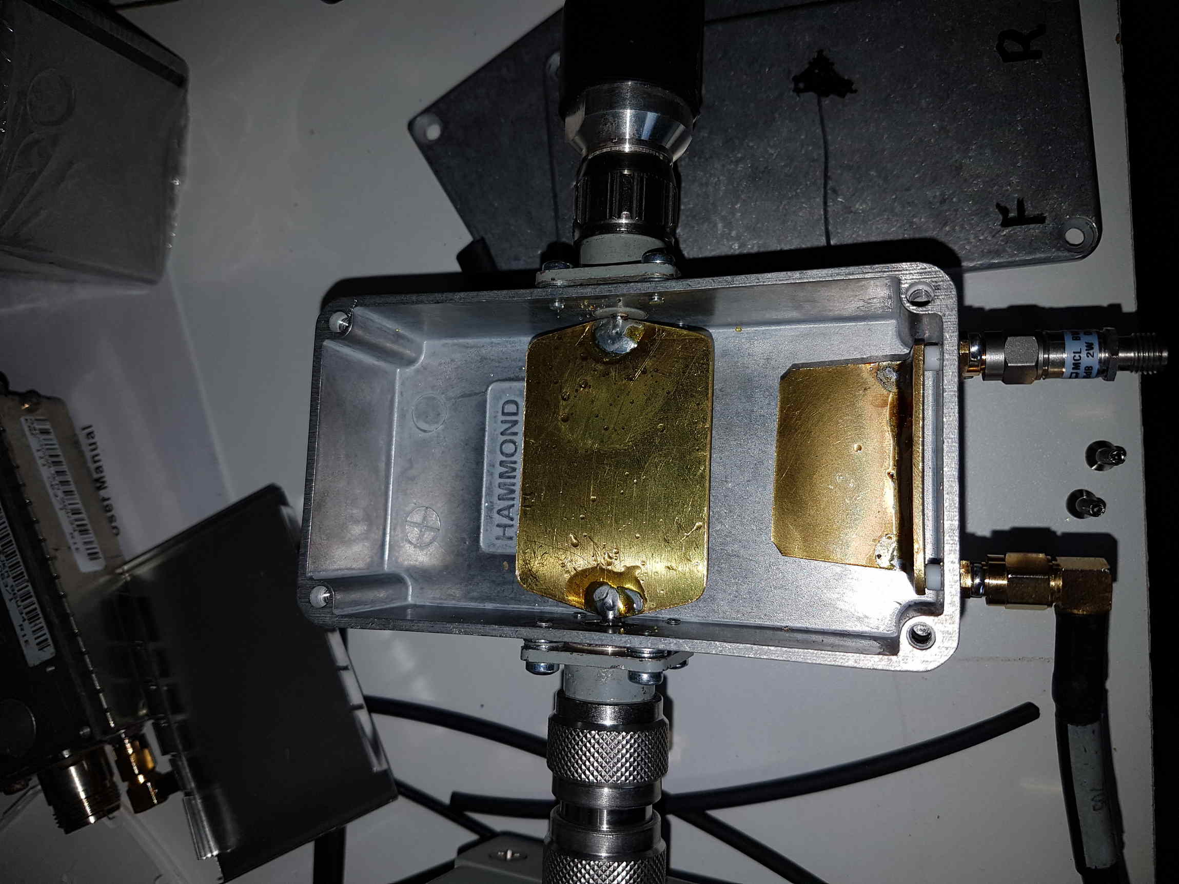
Then I made a simple aluminium box with input and output holes for the RF connectors. After mounting all together amazing what that module could do.
Nice gain, linear, stable and compact.
The complete setup was first mounted on a large aluminium heat sink. Later followed by a 10 mm thickness copper plate to improve cooling.
DANGER-TAKE CARE !!!
I then also found out that it was really important to screen the PA totally. It really needs proper screening. When not properly screened my Raspberry Pi camera did crazy things.
The Spectrian low-power amplifier also was sensitive for the RFI/EMI from the opened PA.
But also the human body nearby the PA receives RF power. Like you are near a bad screened magnetron.
I do remember experiments (long time ago) with an 4CX250 linear amplifier on 432 MHz. Because of too much Teflon isolation near the anode screening, the housing was not screened for RF properly. When a fluorescent tube (TL-tube) came nearby it lighted up. So carefully with RF power nearby.
So now all my PA’s are within a screened box !!
NEW PA SETUP
After I received the first ROGERS PCB’s I started to mill a copper baseplate.
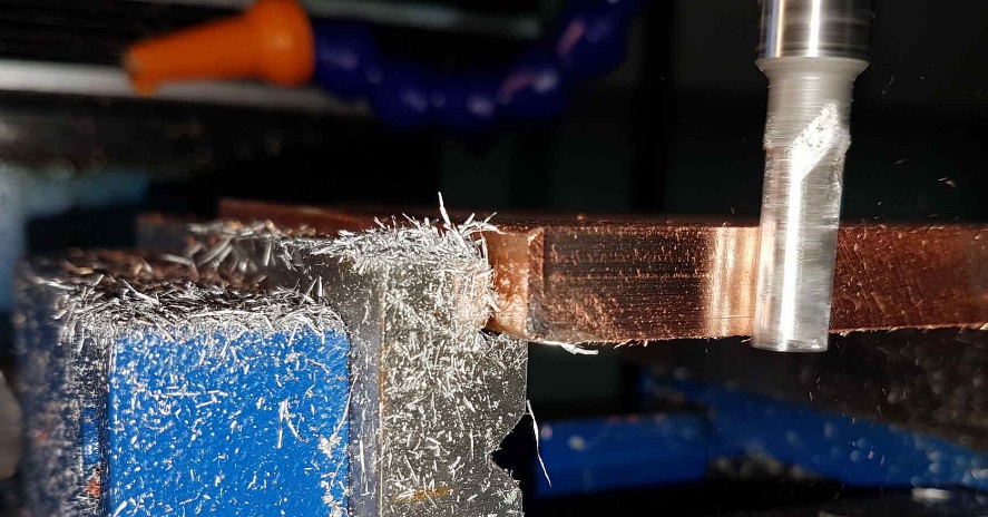
On the long side of the copper plate I mounted aluminium strips to make the mechanical setup robust.
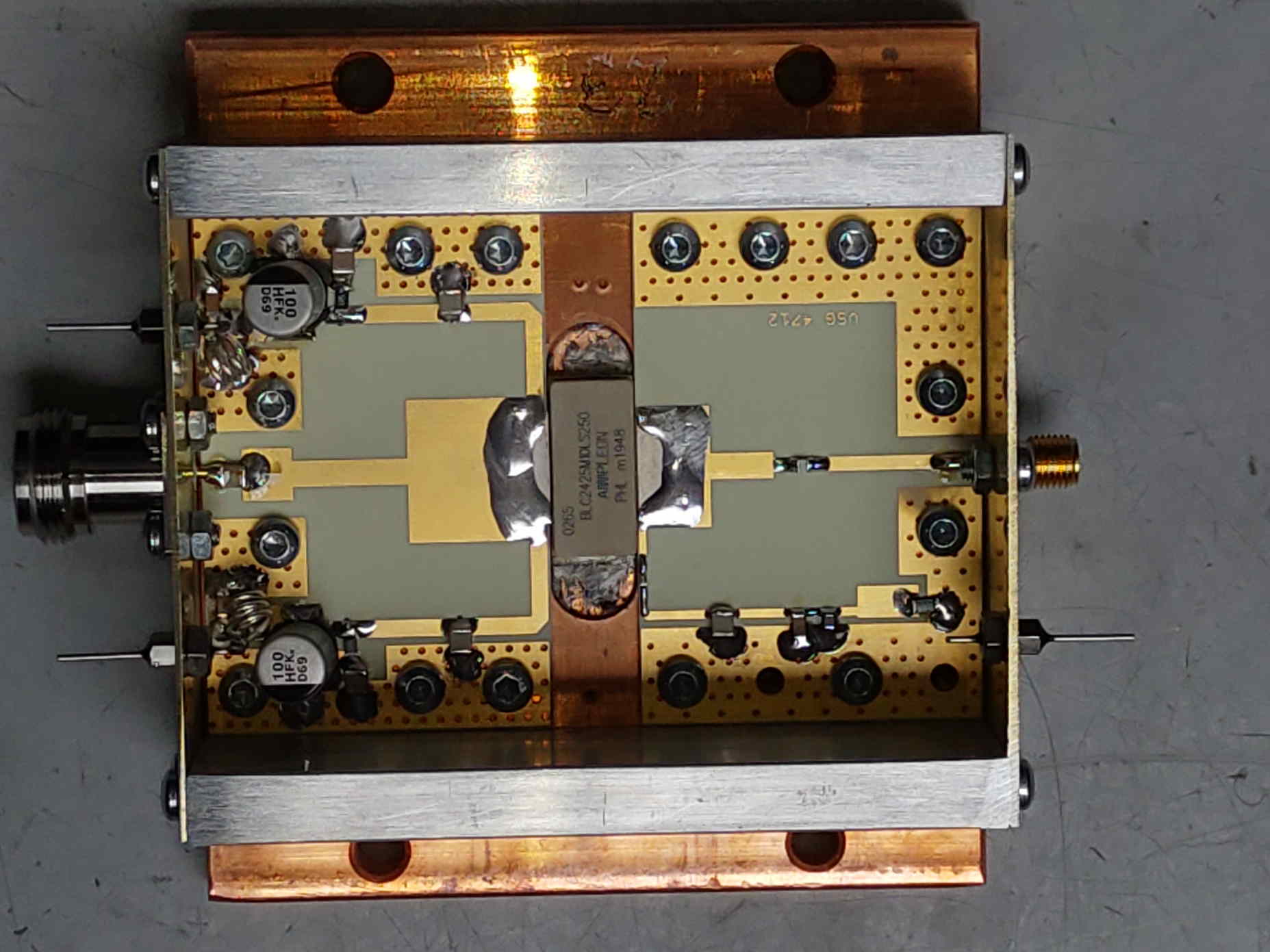
Here a picture of the ROGERS PCB’s used in the first 10 DATV amplifiers:
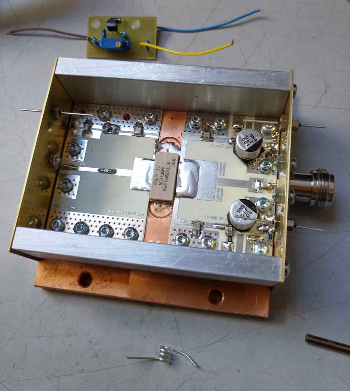
This is a pcb out of the first series of the DATV amplifier.The present PCB’s are gold=plated and have minor modifications.
The small epoxy PCB is the adjustable BAIS circuit and fits in the amplifier housing.
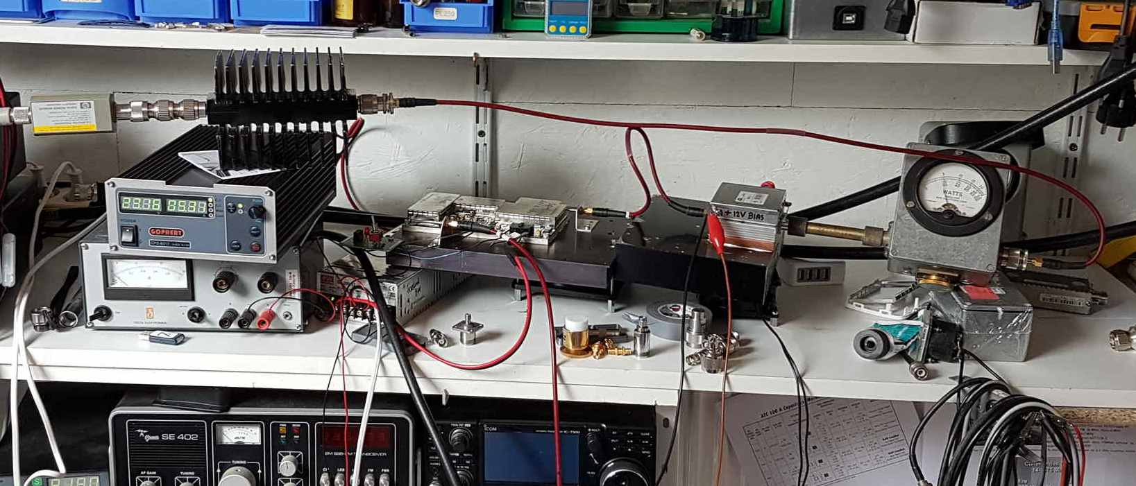
HIGH POWER RF MEASURING
My Bird-slug on the input Bird Wattmeter is 25 Watt 1700-2300 MHz.
The output Bird-slug is 50 Watt 1700 – 2200 MHz. At SR 250 i have nice picture above 35 Watt at H264 and H265
It was only possible to measure with my BIRD watt meter and a 13 cm sensorhead up to 50 Watt.
After completing W1GHZ’s high power coupler i noticed about 40 dB less level at the SMA output,
Some changes were made:
I soldered a brass plate with thickness of about 0,7 mm on the original measuring bar. (the 40 db bar in W1GHZ’s setup) And in the direction of the original coupler plate.
Now i have about 25 dB coupler attenuation at the output, so a nice signal to calculate real output power with my HP RF Power-meter
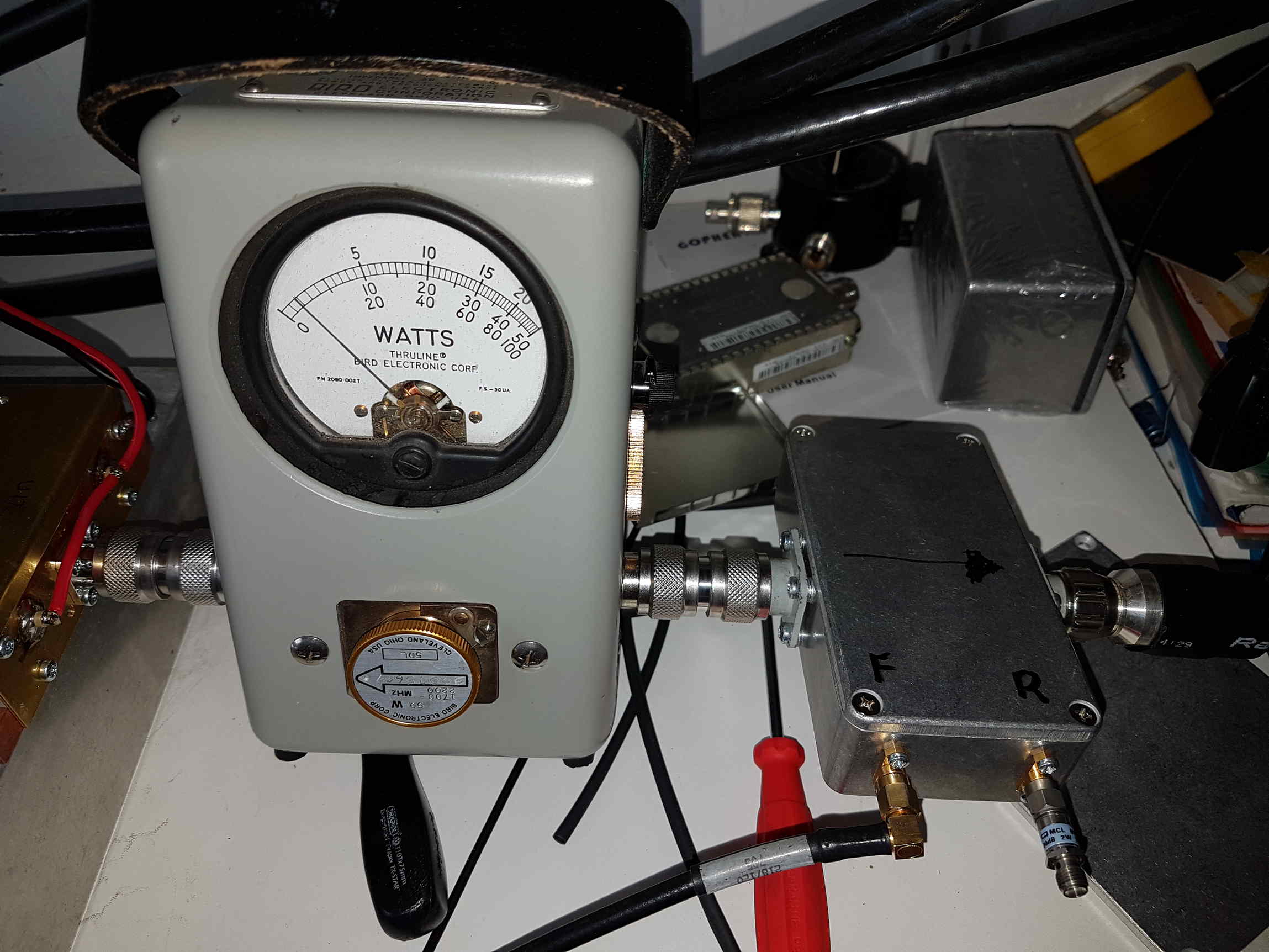
For returned power i use a 50 Watt Bird-slug. With about 110 Watt RF output I have 3 Watt back from coax and dish-feed..
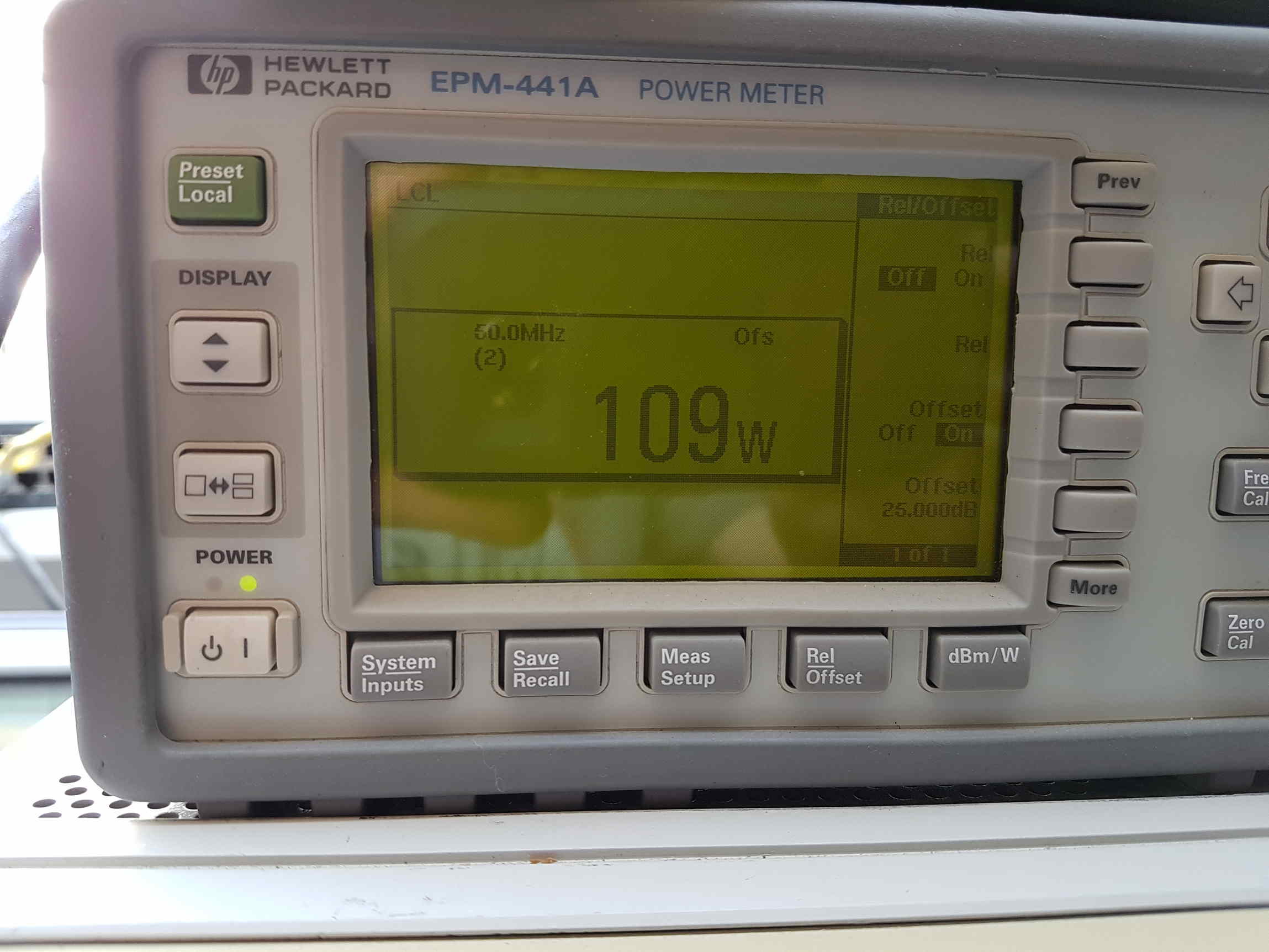
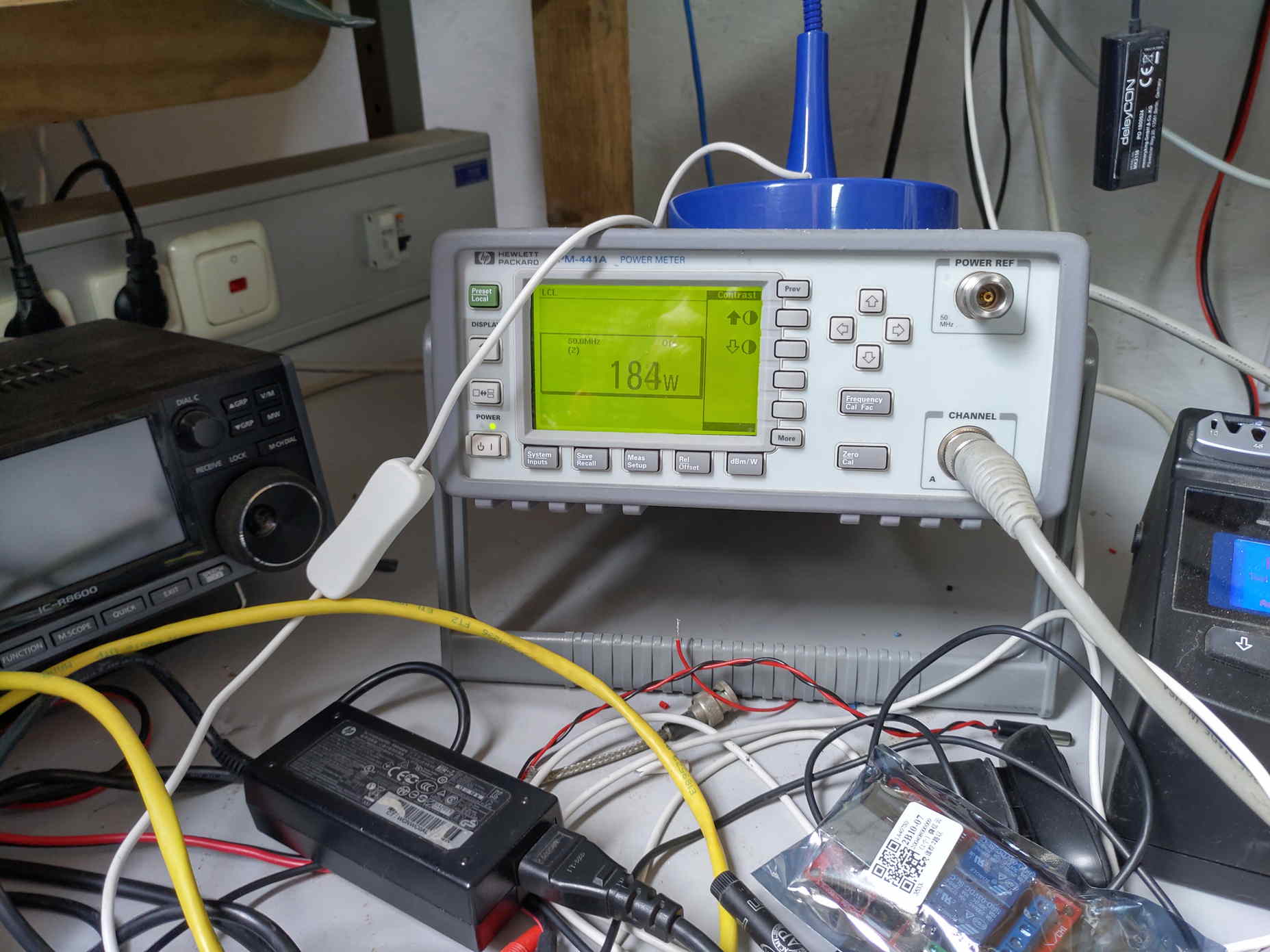
With the HP EPM-441A i can adjust the offset level. The corrected power output is shown at the display!!
Update early 2020, I found out that this coupler setup was improper for a 50 Ohm transmission line. There was some powerloss !!
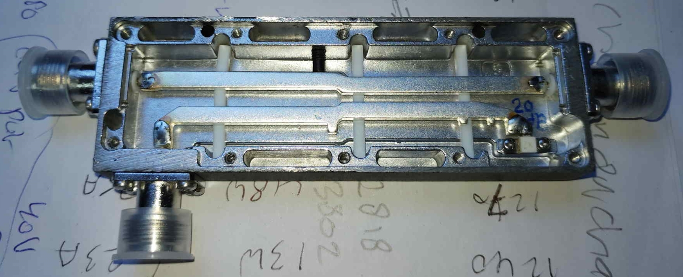
After i found nice RF POWER-COUPLERS on E-bay i stopped using the home made coupler and started to use the standard couplers available in 10, 20, 30 and 40 dB
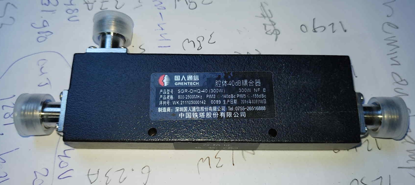
At present i am using these couplers in combination to my HP-EPM RF Powermeter.
To be sure of correct measurements, also an ANRITSU Sitemaster 331 is used to be sure.
But also it is possible to use a BIRD RF powermeter.
When you have a proper BIRD-SLUG for 2400 MHz no problem.
My BIRD’s sensor head covers 2200-2300 MHz and when using a 10 dB Power coupler i get ~~ 30% less RF readout compared with the above described way.
and my readout on the HP Powermeter:
Or the Bird measurements:
Here for measuring returned energy from the load.
When all measurement are ready, remove your coupler with a low coupling factor, a 10 dB type consumes 10% of your RF output 🙂
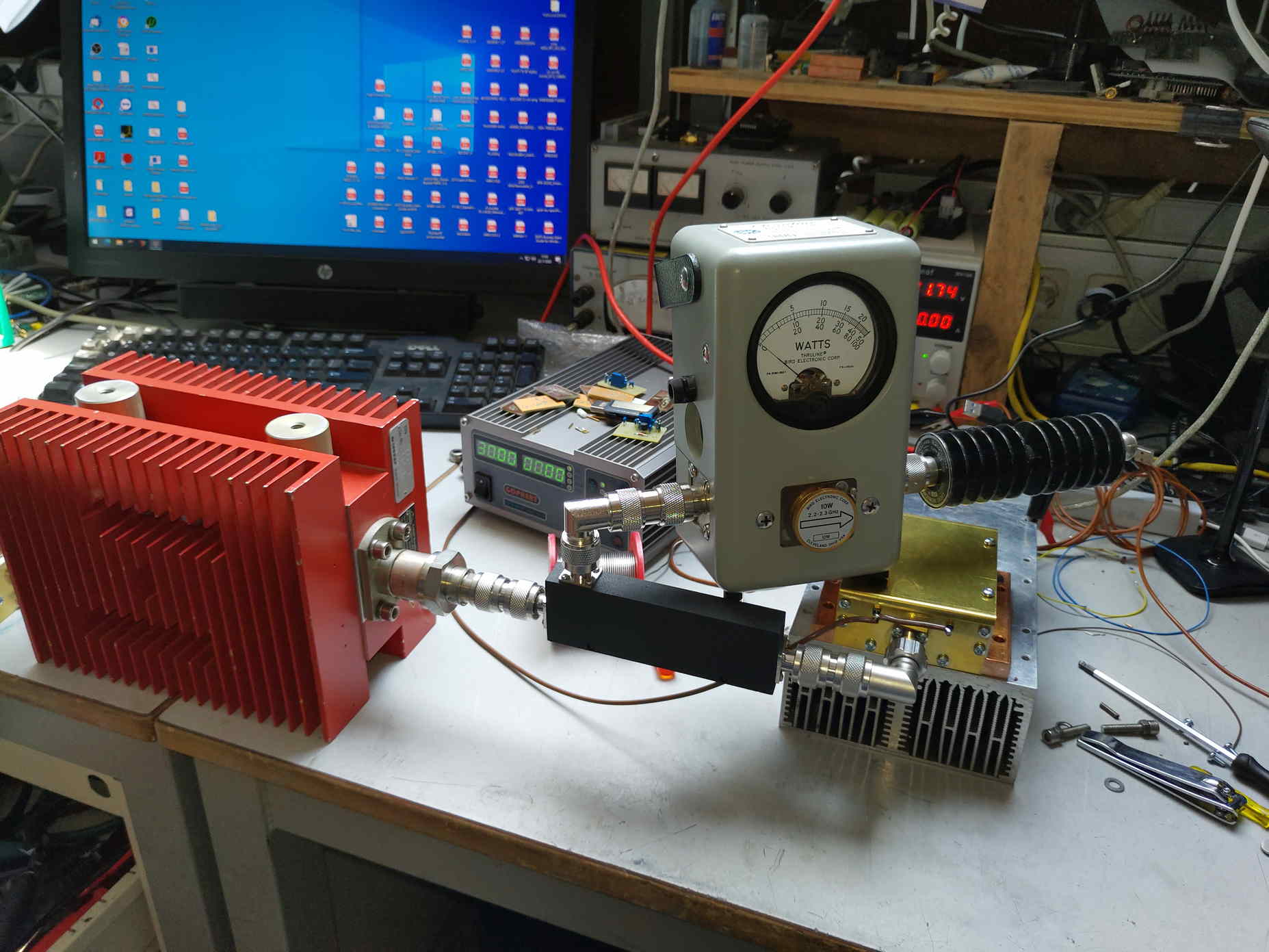
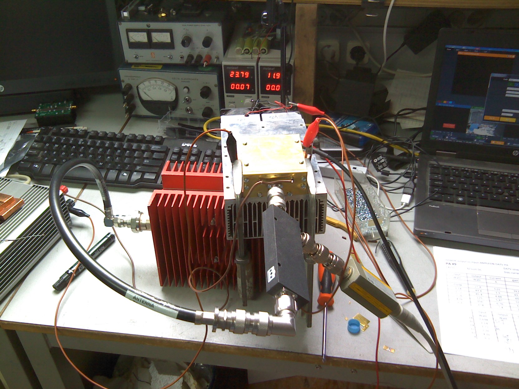
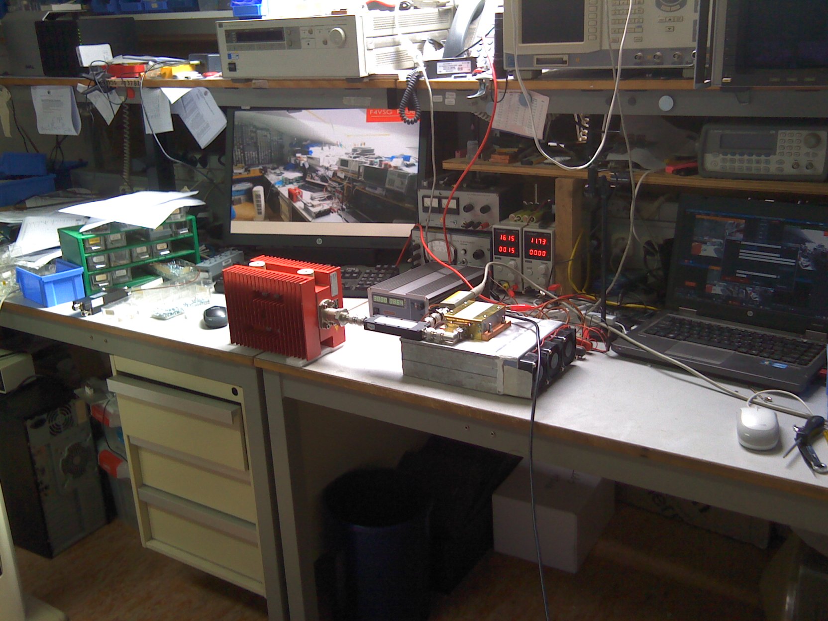
This setup is used for measurements with the DATV Power Amplifiers.
Here an example of FORWARD power measurements.
400 Watt SPINNER dummyload.
It is a “must” to have a proper dummy-load for real testing. Previously i had only a NARDA 150 Watt type, but i found the SPINNER on a radio-flee marked at it made my day !!
Coaxial connections:
I am using high quality N-connectors and adapters. Do not try this with the cheap ”fake” brand connectors !!
Use short cabling from the amplifier to your dish-feed.
Use quality cabling.
NO RG 213 !!
proper cabling:
Cellflex LCF12-50J (or better)
Rosen 400 or CNT/400 for short cabling
Look into the specs before selecting the output cable.
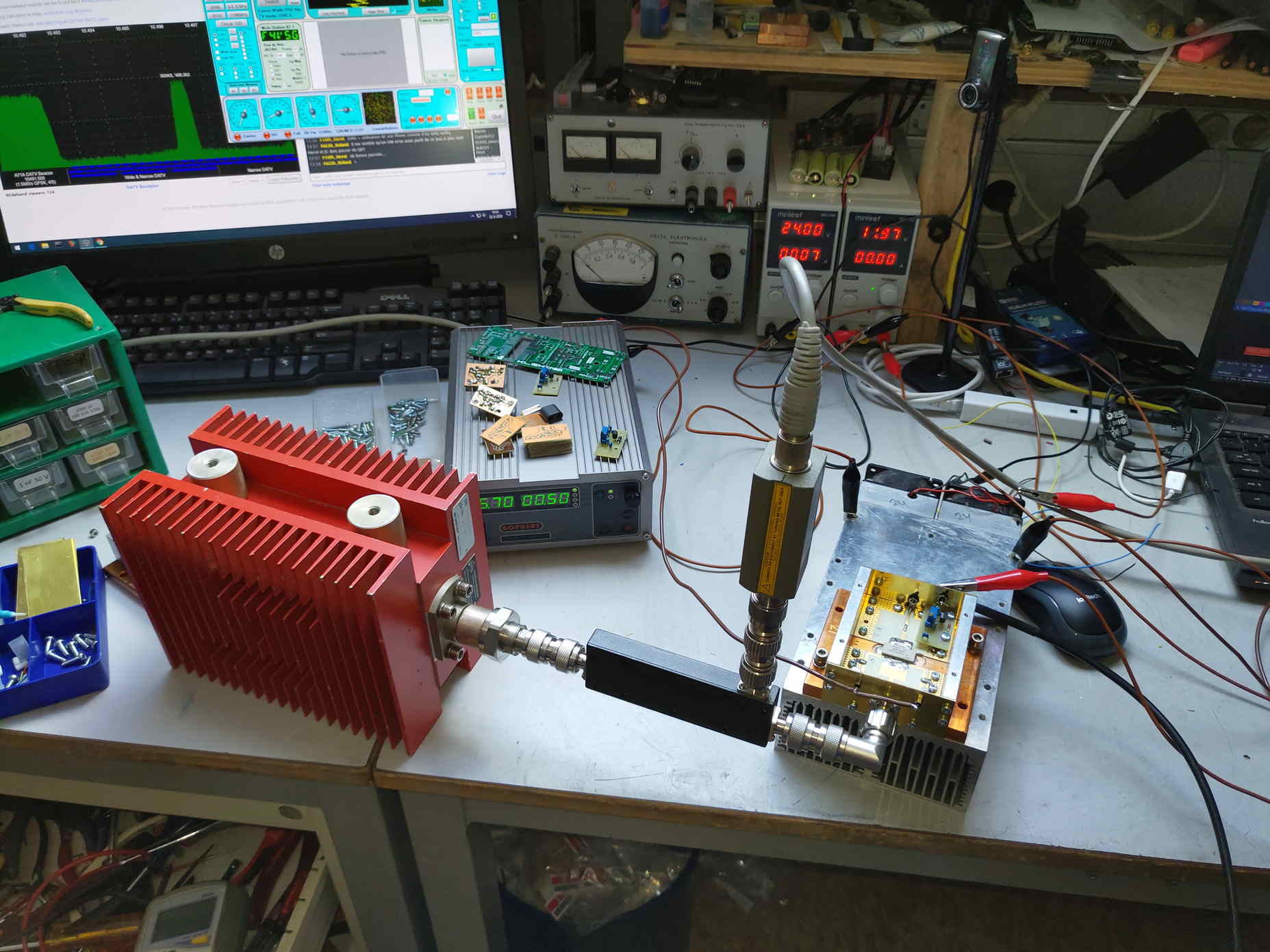
When using coaxial cables this was my previous setup:
As you can see I am using large power the coaxial cable at the output of the coupler towards the SPINNER dummy-load is getting warm.
So now i prefer the setup with N-connector adapters.
In the first time building DATV Power amplifiers i adjusted the BIAS circuitry to an (DRAIN) idle current of 500 mA. This level produces a high linear amplification of input signals.
Also on high power no shoulders !!
I have been experimenting with larger idle current.
Observe the difference in amplification and RF power output:
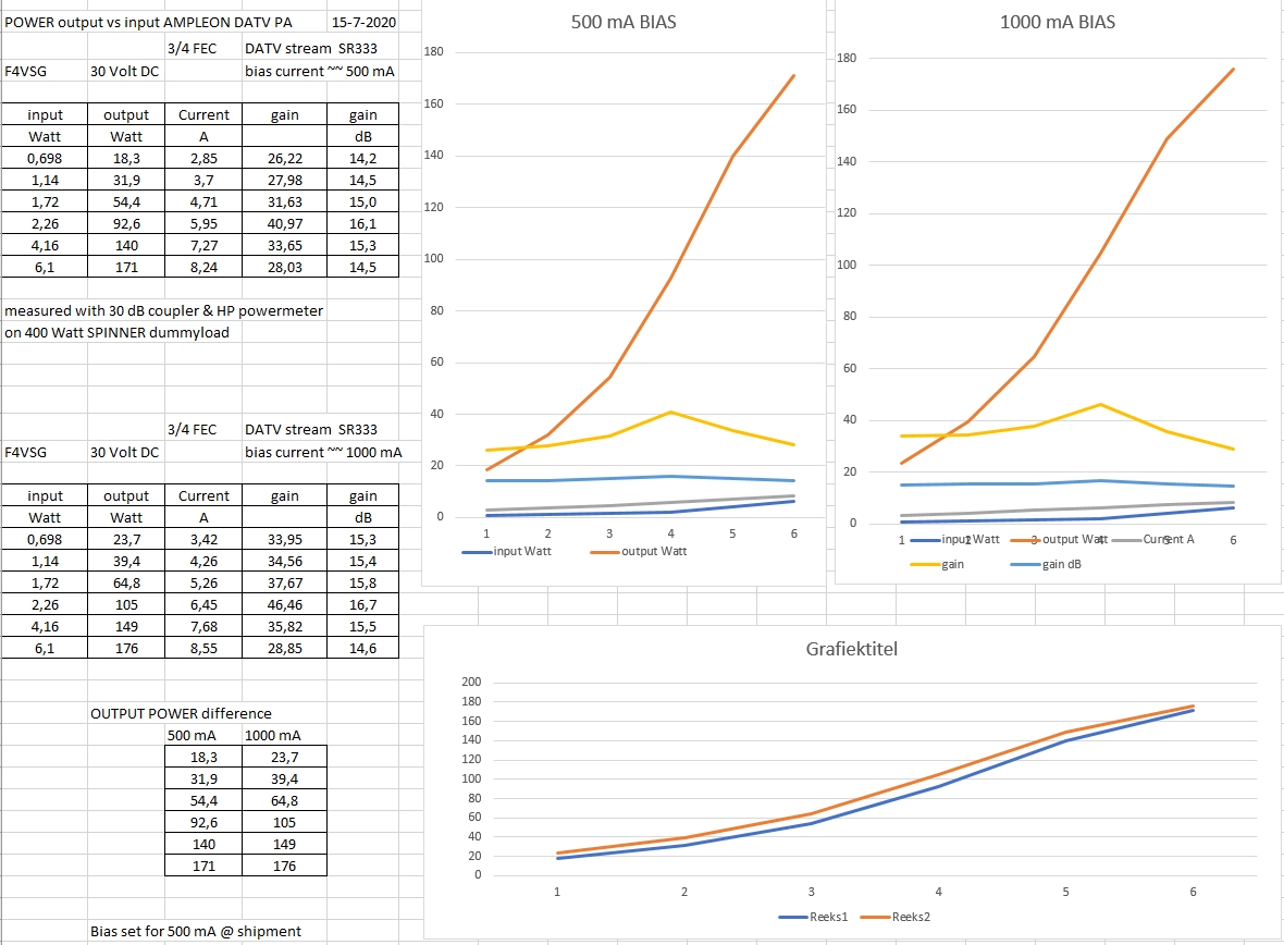
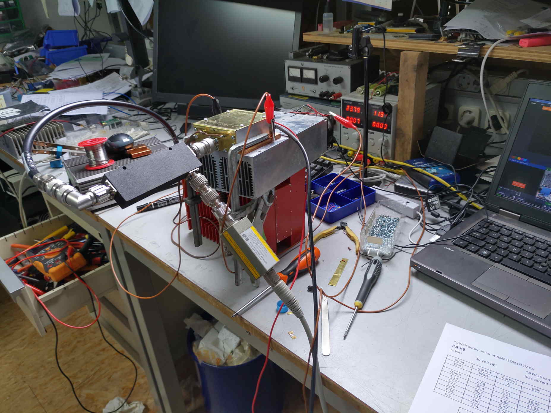
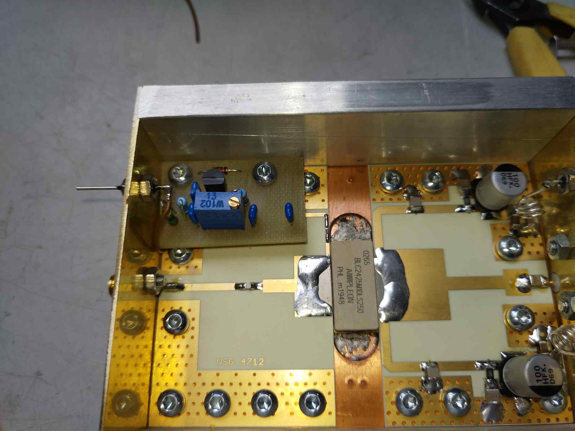
Foto of present test PA without the top cover.
The Bias circuitry is not yet mounted in the amplifier.
Here the BIAS circuitry with adjustable Gate Voltage.
The setup of the amplifier is robust. Use a proper heatsink and use heatsink- compound in between the copper base-plate and your heatsink.
Furthermore use one or two ventilator to have an airflow to cool down your heatsink.
During normal transmissions my ”tunnel type” heatsink is around 35 degrees Celsius.
When i have long duration tests with a DATV amplifier on Dummyload it goes up a little in temperature.
When RX-ing i remove the 12 Volt from the BIAS input. The amplifier can cool down.
Tips for a proper heatsink:
Take a ~~ 20*20cm heatsink with long flaps.
Mount an aluminium plate under all the flaps so a kind op tunnel will be created.
Mount some blowers at one side of the tunnel.
Or:
 Here a real tunnel type of heatsink is used as constructed for Charly´s DATV Amplifier 🙂
One side of the tunnel houses 3 60*60 mm ventilators (25 mm height, 24 Volt)
I made an aluminium plate, removed some aluminium-plate in the corners, bended the aluminium so a cap was constructed to be mounted on the tunnel. After that i made 3 holes of ~~ 55 mm and mounted the 3 fans.
After connecting all together i lowered the voltage to ~~ 18 Volt because of plenty of airflow. (and less noise)
The heatsink and copper bottomplate/DATV Power Amplifier stays really cool.
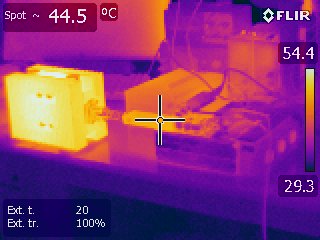
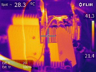
See the thermal image with a dummyload test @ 180 Watt after half an hour.
Notice the temperature of the 200 Watt RF power-coupler it is ~~ 45 degrees C.
The dummyload is approx. 55 degrees C.
Just behind the coupler you see some thermal activity, this is my 30 Volt powersupply.
Right-aside the power coupler is the tunnel type heatsink. almost cold 🙂
Further used equipment here:
JETSON Nano H264 en H265 system gives a fast stabile picure on the OSCAR-100
I am using the Jetson-Nano with script use Linux script and a Raspberry Pi Camera.
Update mid 2020 I am also using an ADALM Pluto with Evariste’s F5OEO firmware. Really nice and simple to use.
In the stream-setup in the V-MIX program the RF level towards the DATV amplifier can be adjusted at an easy way.
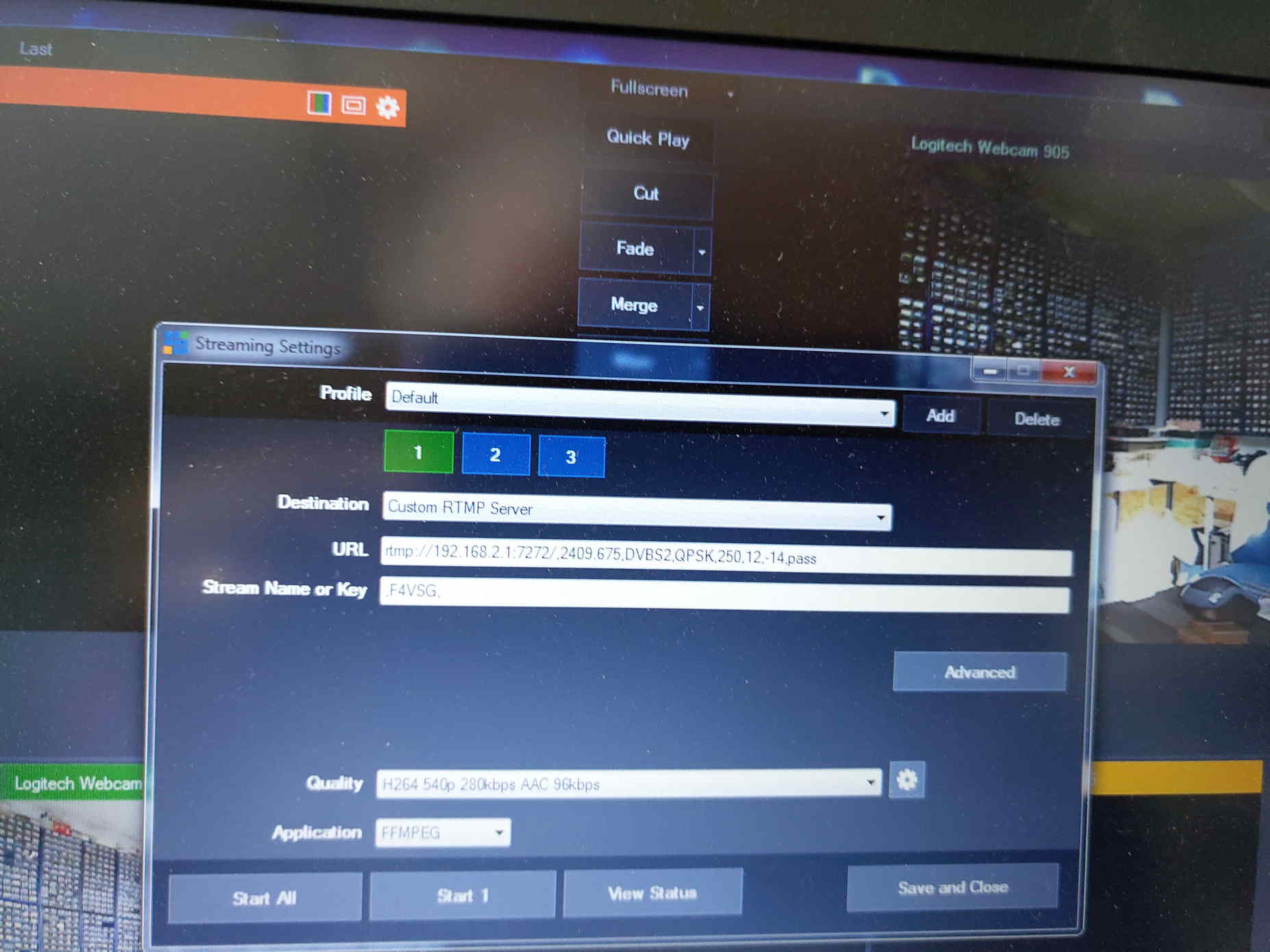
The -14 number is the RF output setting of the RF-level.
After the ADALM-PLUTO i have some amplification. I can make up to ~~ 10 Watt RF level to be able to measure DATV Power amplifiers under various conditions.
At these high-frequencies the capacitance of the Powerfet changes under the used voltage. At a ”low” voltage the Drain-Source capacitance is a little bit higher then by 30 Volt.
At 2400 MHz each little bit of capacitance changes the output “”tuning”” of the circuitry.
The DATV amplifier is optimized for 30 Volt. I know the AMPLEON device is capable of running at 32 Volt, But be honest half a dB more RF output and during a power glitch a broken RF Powerfet, you are not happy !!!.
Use the amplifier at 30 Volt DC.
Use an Ampere meter to observe the DRAIN current.
And a rule of thumb, 50 % of the fet’s power output seems a proper value for clean undisturbed amplification.
The AMPLEON BLC 2425M10LS250 is specified for 250 Watt RF output level.
In the setup used it is a good idea not to go over the 150 Watt output level. It really can do more, but do you need that amount of power ??
A good combination of a antenna and proper short cables is a good idea to reduce the RF level.
I also tested the DATV PA in my 2320 transmitter chain during a contest. Well over 100 Watt RF output power !! I am happy again.
Extra tips: CLICK hereunder !!
your received AMPLEON POWER-amplifier ver 27-7-20
Will be continued at short term !! (july 27 2020 version)
73 Robert.
October 29 2020 New info:
After i bought a small mini VNA i have been optimizing the input setup of the DATV power amplifier and the frequency behaviour of the used RF Power-couplers.
Here the measurement-plot of a 200 Watt 800-2500 MHz Power coupler:
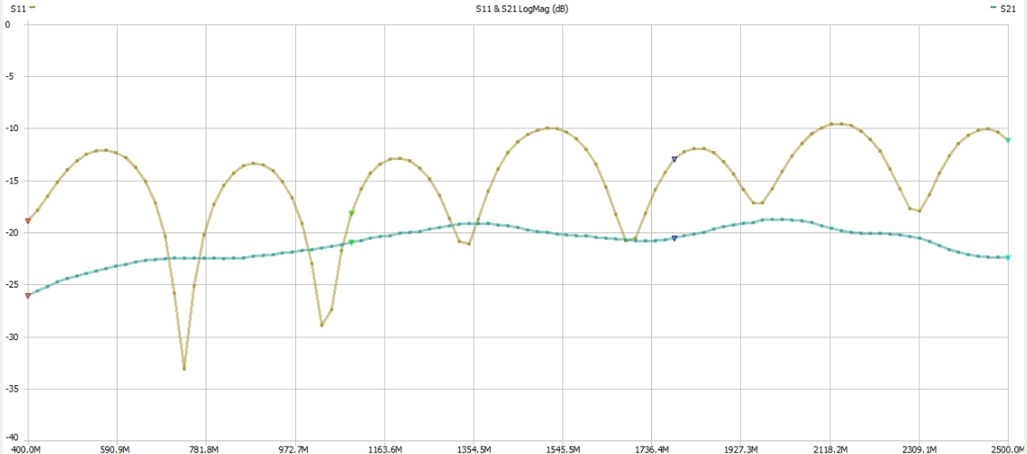
The blue line is the RF-coupling factor.
@ 2400 MHz ~2dB difference.
It is important to calibrate the used coupler!!
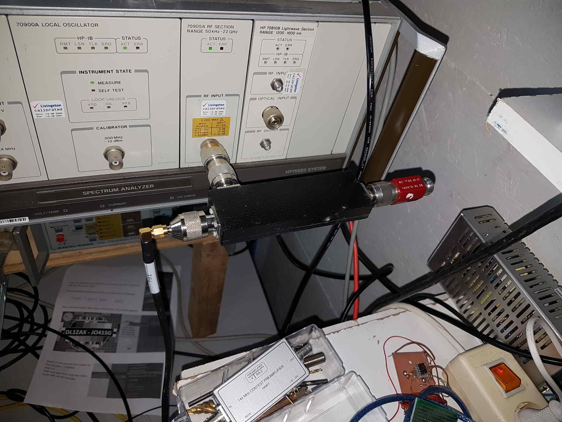
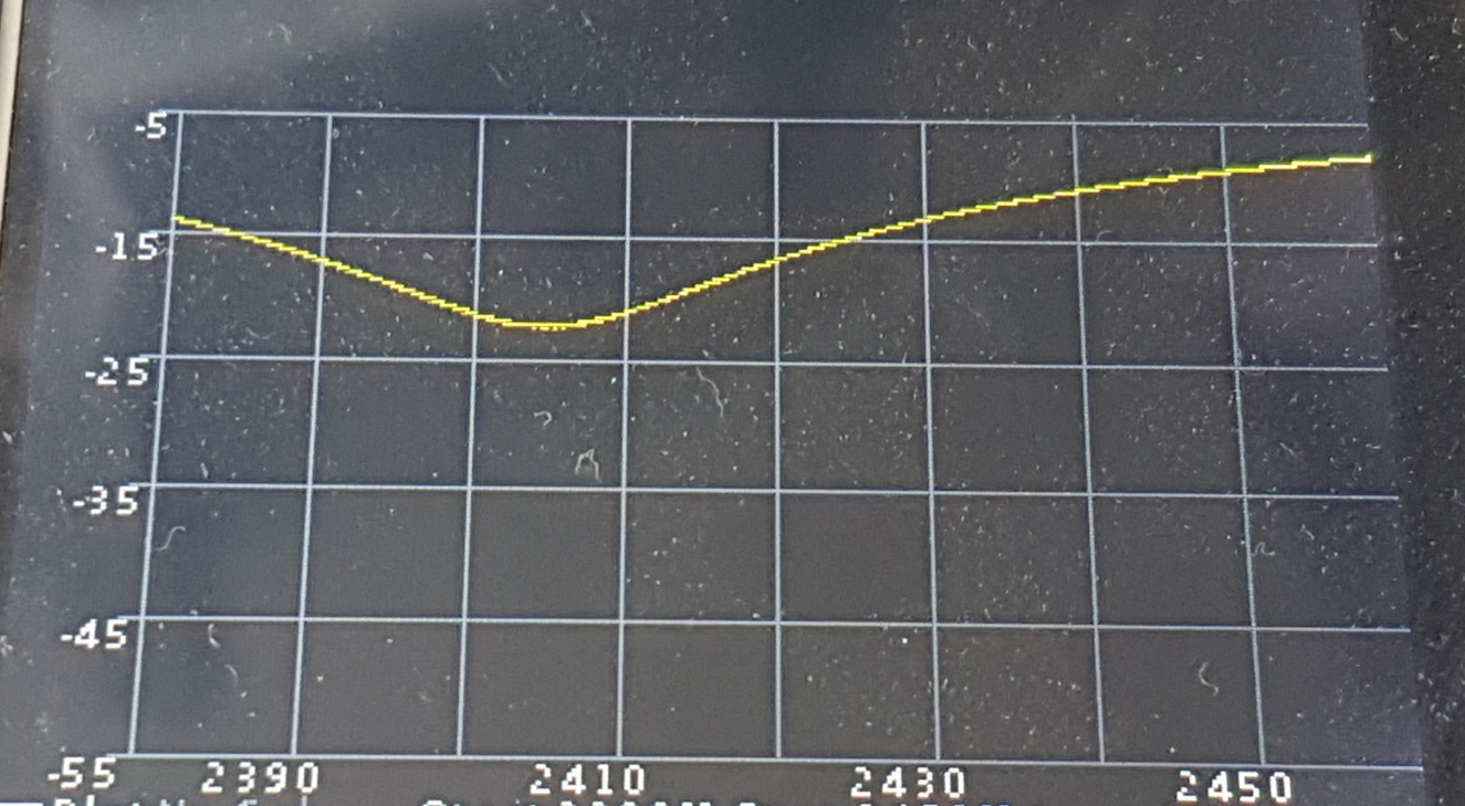
After warming up my Spectrum analyser and the signal generator for some time i adjusted a signal on 2400 MHz to the spectrum analyser and set the level to -10 dB.
Then i connected the coupler to the analyser and used the same cable.
At the RF-output of the coupler a proper 50 Ohm load.
For the 30 dB coupler in use i set the small adjustment screw (hidden behind a sticker) on a level of – 40 dB. (a difference of 30 dB !!)
Now i am happy again.
I also used the VNA to optimise the input circuit of the DATV Power-amplifier.
After this action a I have a little more power output from the amplifier !!!
At present i am using OBS with ADALM-Pluto with Evariste’s firmware ”for the brave”.
Recently i made an upgrade to new firmware ( F5UII ) Now i have sound again when using the H264/H265 encoder.
But i had the idea that it looks i have a little different RF level towards the DATV Power-amplifier.
So i performed a new measurement to be sure that the input level of the amplifier is the real level !!.
Behind the Pluto i have one pre-driver and that output signal is connected to a “”small”” SPECTRIAN amplifier.
That’s the input to the AMPLEON DATV power-amplifier…
More to come
73 to all
Robert F4VSG
