some of my DATV activities
DATV reception and I/Q modulators for 70, 23, 13 and 10 GHz.
Great development/technique, the minitutione arrived, so I directly made a PCB setup and etched a PCB.
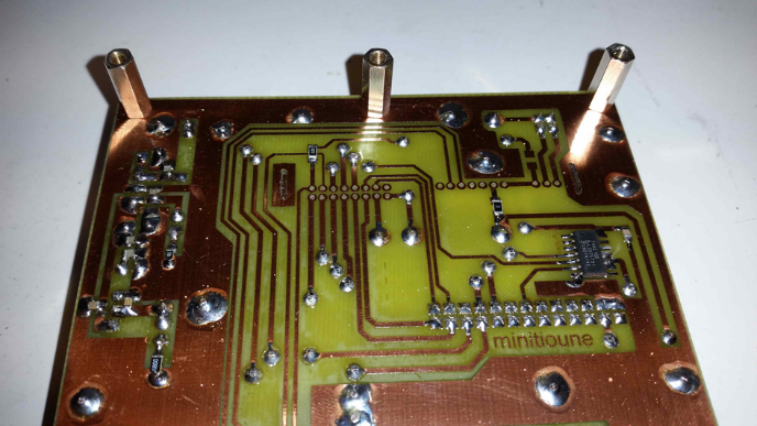
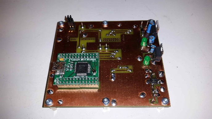
bottom and top of Tutioune 1
My start was at 437 MHz reception.
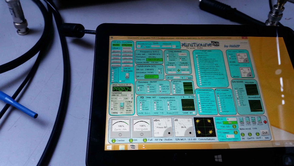
After a short term my Tutioune reception was OK.
I used a 2400 MHz. converter to enable 70 cm reception.
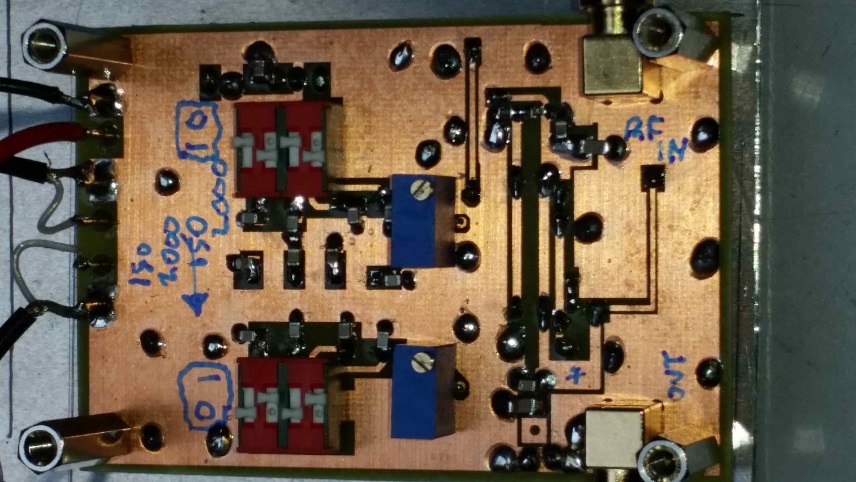
First I also used an extra preamp
The 70 cm spectrum received from F5ZVQ at a little over 100 kilometer distance of me.

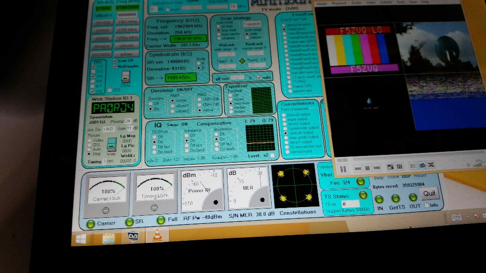
And Tutioune overview of received F5ZVQ repeater Crêt Monniot
No difficult components. Now it is possible to receive lo SR DATV signals !!
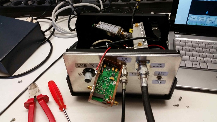
The tytioune build together in a metal cabinet here together with a VLNA preamp.
TRANSMITTING on 70 cm, but first the I/Q modulator !!
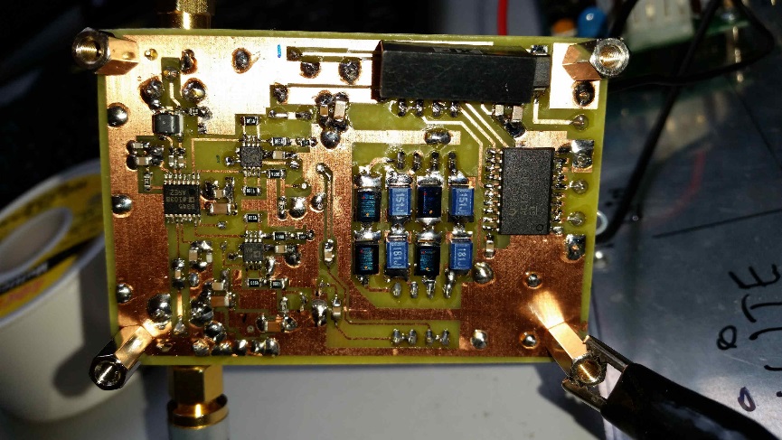
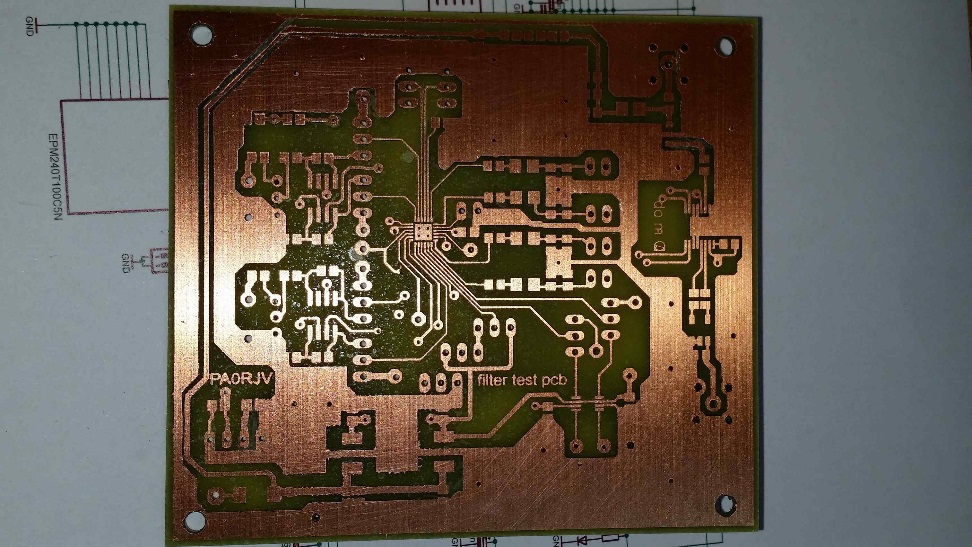
Here the first prototype of my I/Q modulator, including two seperate stages of nyquist filtering after the Digilite idea.
I/Q modulator with seperate nyquist PCB
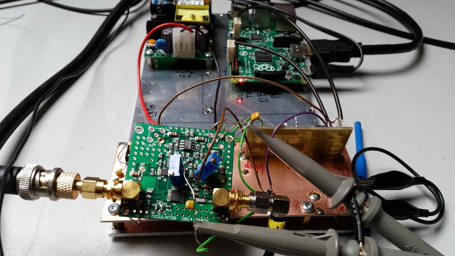
Working prototype of first I/Q modulator 1
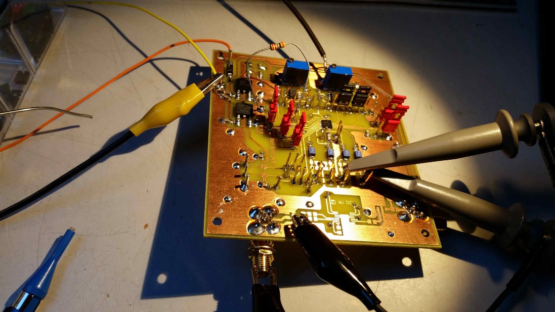
Experimenting with nyquist filtering adjustable over a large SR area.
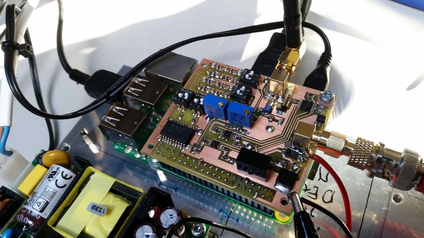
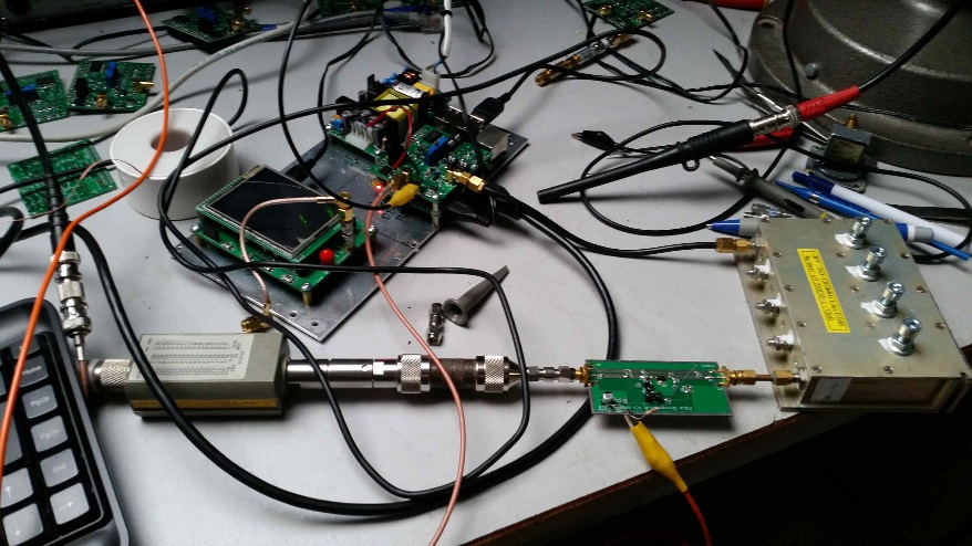
DATV transmitter system for 437 MHz.

DATV I/Q generation, frequency filtering, and Mitsubishi PA stage
DATV transmitter for 23 cm
Simple setup with I/Q modulator frequency filtering and some extra amplification.
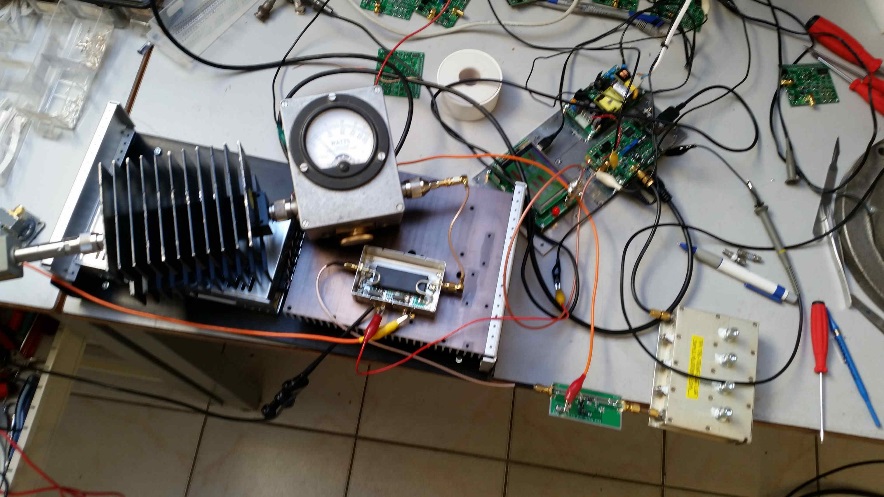
Also here I/Q modulator now with filter and PA stage
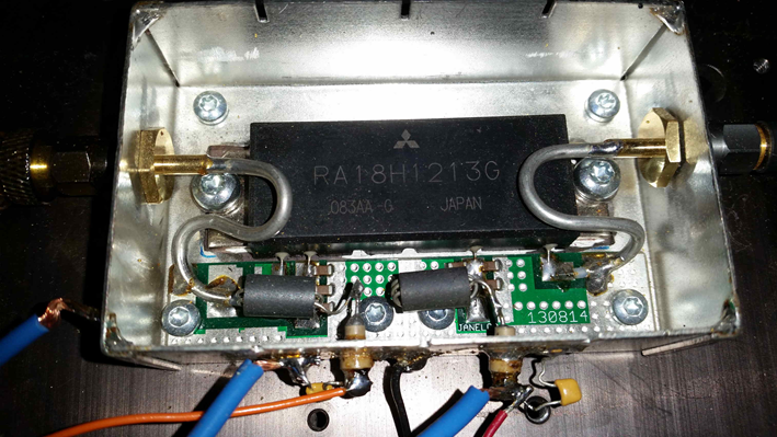
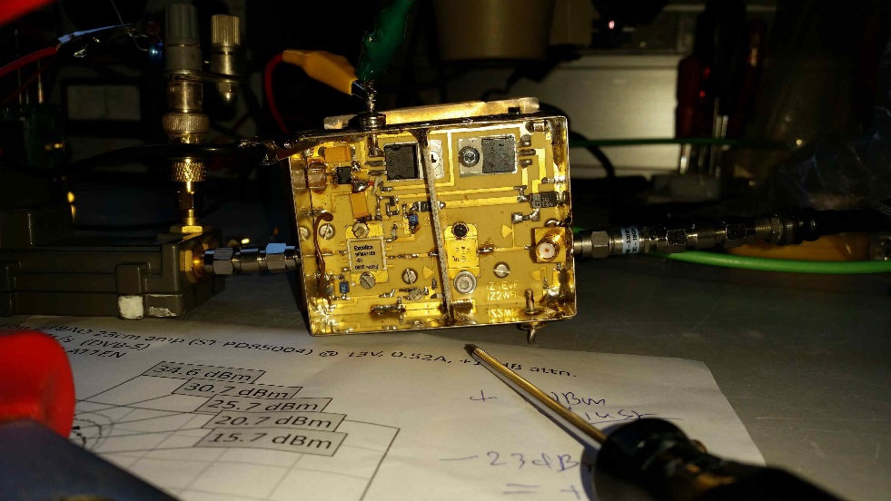
The 23 cm PA using a Mitsubishi module.
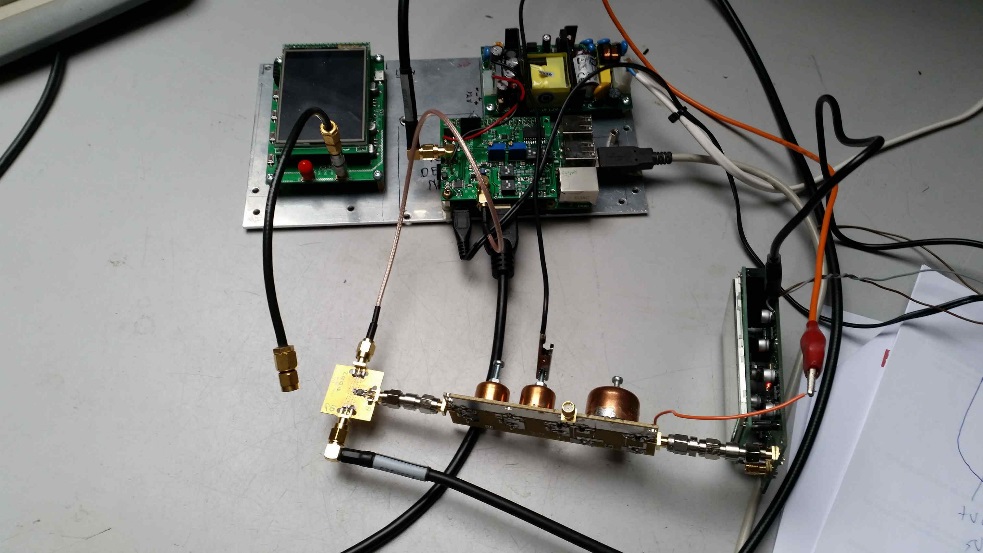
DATV Transmitter setup for 10 GHZ
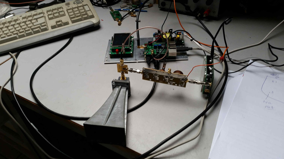
2250 MHz generation with ADF frequency generator.
Multiplied in the pipe-cap filter unit. 4500 MHz output to the mixer module (the small pcb near the 10 GHz horn)
The input frequency is multiplied to 9000 MHz in the mixer chip. . So when TX on 10.250 GHz the DATV input is on 10250-(2*4500) gives 1250 MHz, simple to make.
Furthermore 9000 MHz -1250 MHz is filtered easy in the stages followed by the mixer.
Total result a clean TX signal !
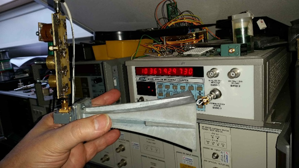
And Power output shown at the frequency counter !!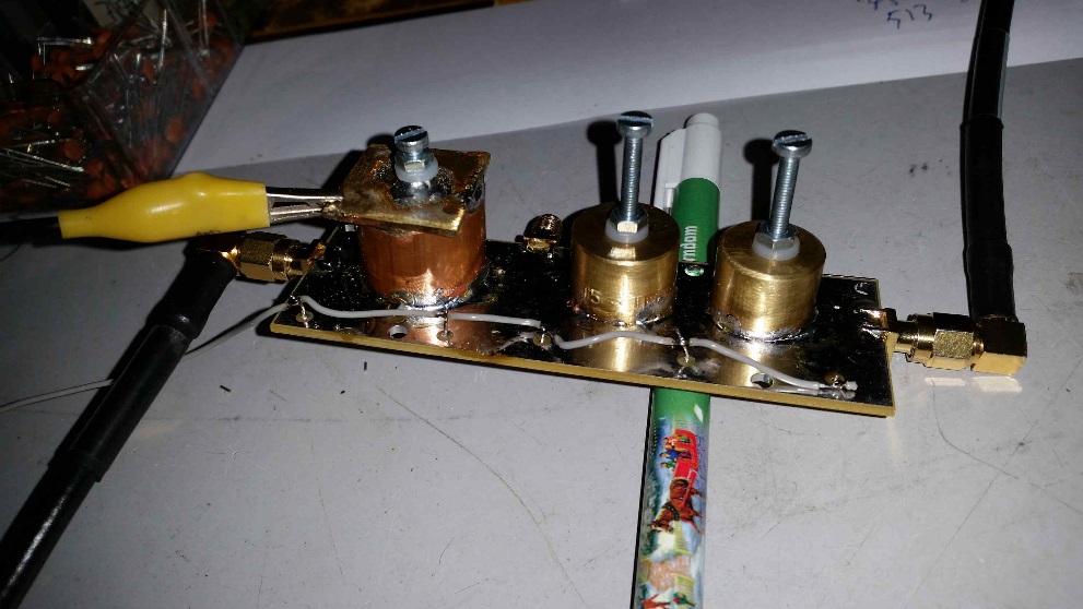
The pipe-cap amp and filtering stage.
First signals with only 10 mW output on 10 GHz could be received at a distance over 7 kilometers over a city area.
The 10 mW was fed into a copper pipe with external diameter of 22 mm. Wall thickness of 1 mm.
A coaxial input with a 1/4 input stub.
At the top of the copper-pipe the identical output stage . From there a short coaxial cable to a 30 cm parabolic dish.
The copper pipe was mounted to an aluminium mast to make it more mechanically strong. The aluminium pipe was also used to rotate the small parabolic reflector in the proper position.
10GHzPA stage
Essential to have some more power !!!