FOR SALE:
TX Sequencers
On the PTT signal the sequencer controls coaxial relays and bias circuitry.
Powersupply 12 Volt DC.
A bad SWR could be detected by the sequencer. (Using the output voltage of your SWR measuring device)
When the adjustable SWR-level is reached the TX is switched off to protect your equipment !!!
I am using the Bird 43. As a matter of fact I am using dual line section as the attachment.
So for power to the antenna i am using an 1 kw element and for the reflected power an 100 watt element.
With let’s say 30 watt reflected the element delivers 260 mVolt to the sequenser swr in.
When the sequencer detects more than 260 mV it will release the ptt and the amplifier stops transmitting.
After the reflected power is corrected, reset the sequenser by removing the supply voltage.
The PCB has a adjustable TX delay.
PRICE complete build and tested € 70
Translation from Dutch Language:
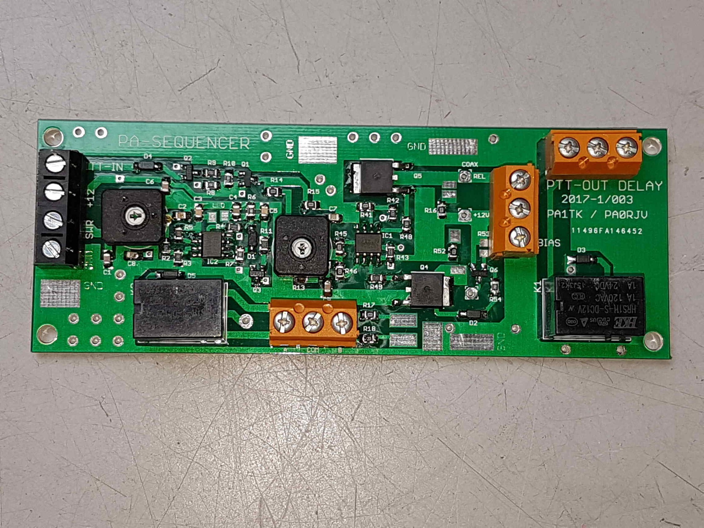
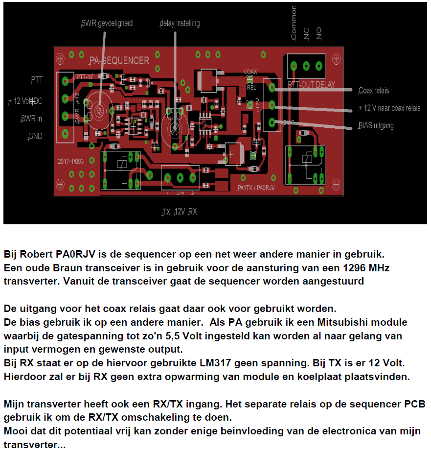
A old Braun transceiver is used to have RF input to the 1296 MHz transverter, On the sequencer PCB there are two relays. one of them has complete floating outputs for more external connections.
BIAS and Relay connections and LED connections can be made using screw-terminals and solder pads (LEDS)
SEQUENCER BOARD
The 4 pin connector has the following connections: A PTT connection B 12 Volt C SWR input D GND
The PTT connection is the interface with the transmitter or transceiver to start transmitting. The input is active (transmit) when the PTT connection makes a connection with GND (earth). A diode is included in the chain as protection. The 12 Volts input is not provided with a protection diode due to variable currents through the circuit if a coax relay or external devices are connected via the additional relays.
Due to variable currents, a small voltage difference may arise on the bias, which may have a slight influence on the quiescent current of the linear amplifier. The 12 Volt input must therefore be connected to a stabilized 12 Volt DC voltage source. The SWR connection will switched off the linear amplifier if the SWR of the antenna is not OK. The protection system is build for the Bird Power sensor which we use. The sensitivity of the SWR signal is adjustable with the potentiometer of 4k7.
The circuit is most insensitive when the potentiometer is fully counterclockwise. The most sensitive if the potentiometer is fully clockwise. A red LED is included in the SWR circuit. This LED is part of the correct operation of the circuit. The LED connection with the long connection (anode) goes to the brown wire. The short connection (cathode) goes to the blue wire. At the moment that the set SWR circuit detects a too high input voltage, the red LED will light up and bias and relay will be switched off from the TX mode.
Resetting this (SWR overload) situation must be done by briefly switching off the sequencer circuit. (de-energizing the 12 Volt) We have built the swr circuit for the Bird swr / power meters that we use. As an example: a 100 watt element gives something of 0.26 Volt at 30 watts of return.
Obviously the swr does not have to be connected and the sequencer also will also function without swr detection; in that case you can remove with the red LED With the help of the setting potentiometer of 47 kOhm, the switch-on delay of coaxial relays and bias is adjustable. The GND connection goes to the GND of the 12 Volt power supply.
There are several connections for optional GND connections on the PCB.
It does not hurt to use these extra GND connections. !! Two relays are also arranged on the printed circuit board. The relay A is in use to be able to switch a pin A or pin B to 12 volts if desired. Pin B = RX status Pin A = TX status Two SMD LEDs are installed on the right side of this relay. RX = green TX = red.
The coax relay can be operated by connecting to the top two contacts of the 3-pole screw connector (+ 12 Volt and COAX-REL) The bottom connection is the BIAS output of 12 Volt. An optional LED can be connected to the solder island above the resistor (anode) and the lower right-hand island that is the drain of the Bias-link-FET (cathode). The second relay is a contact situation that can be used by the user himself. This is often a PTT-out delay circuit. The contacts are potential free. The leftmost connection is the common contact of the relay. The middle contact is the NC contact (closed during RX and open during TX) The most right contact is the NO contact. (open during RX and closed during TX) If you have questions about the circuit, send an e-mail and we will try to respond as soon as possible.
.
.
.
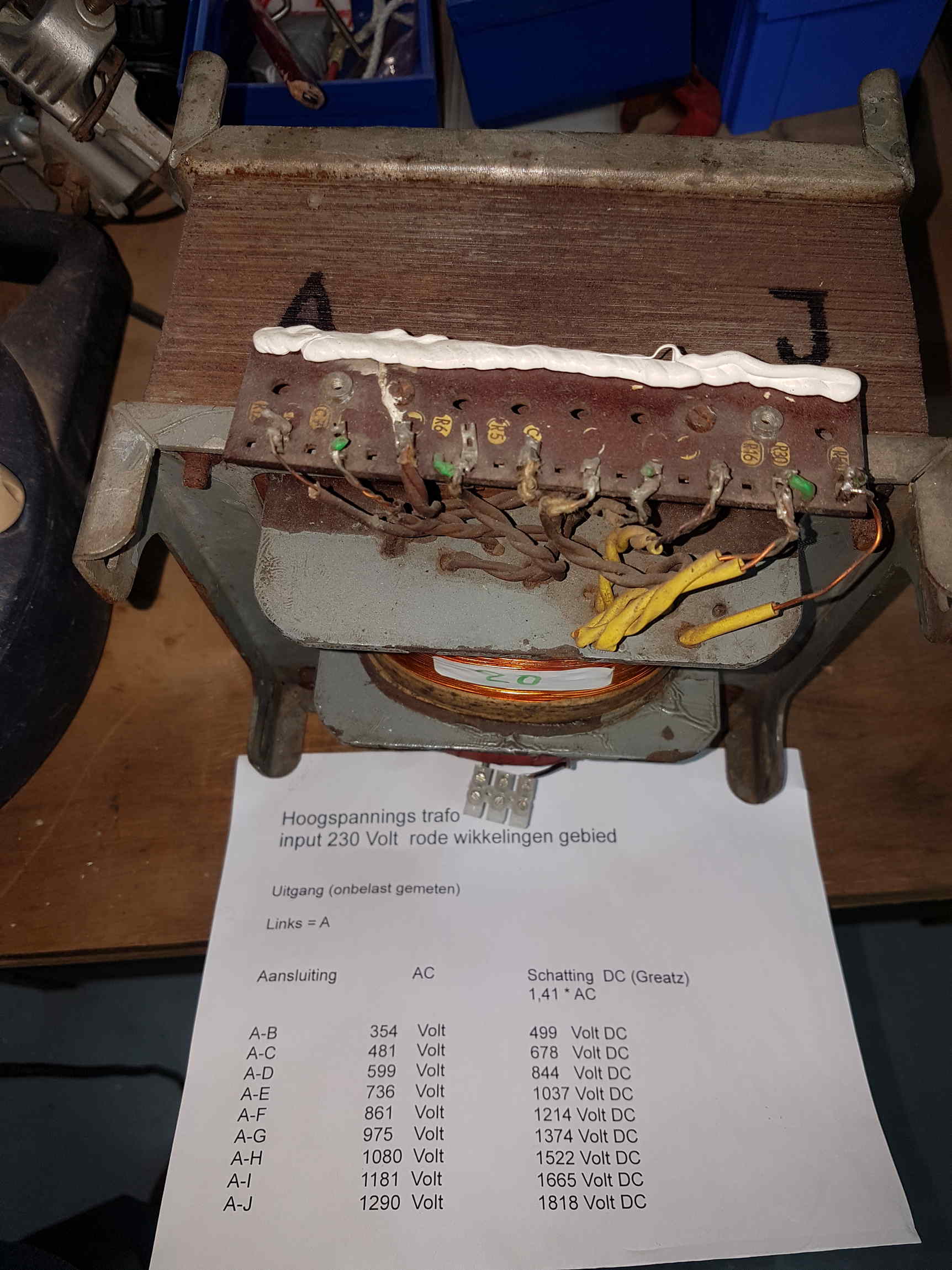
High voltage POWER transformer HEAVY !
primary 230 Volt.
See info on photo for secondary output voltages.
PRICE € 20
.
.
.
Heavy 380>220 (400>230) Volt transformer. 1600VA
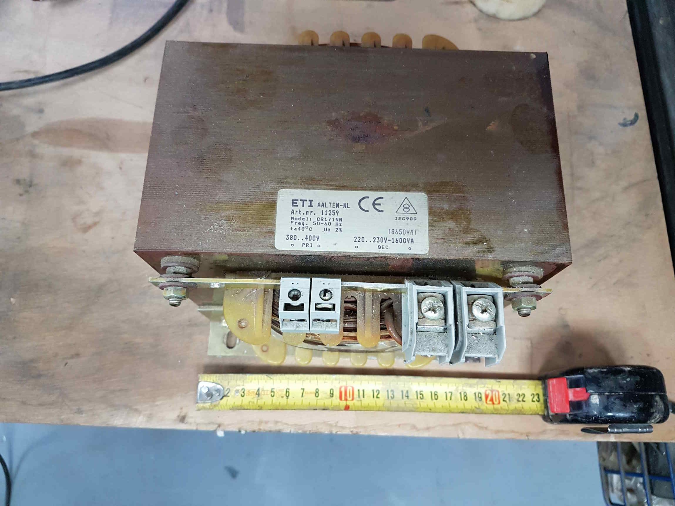
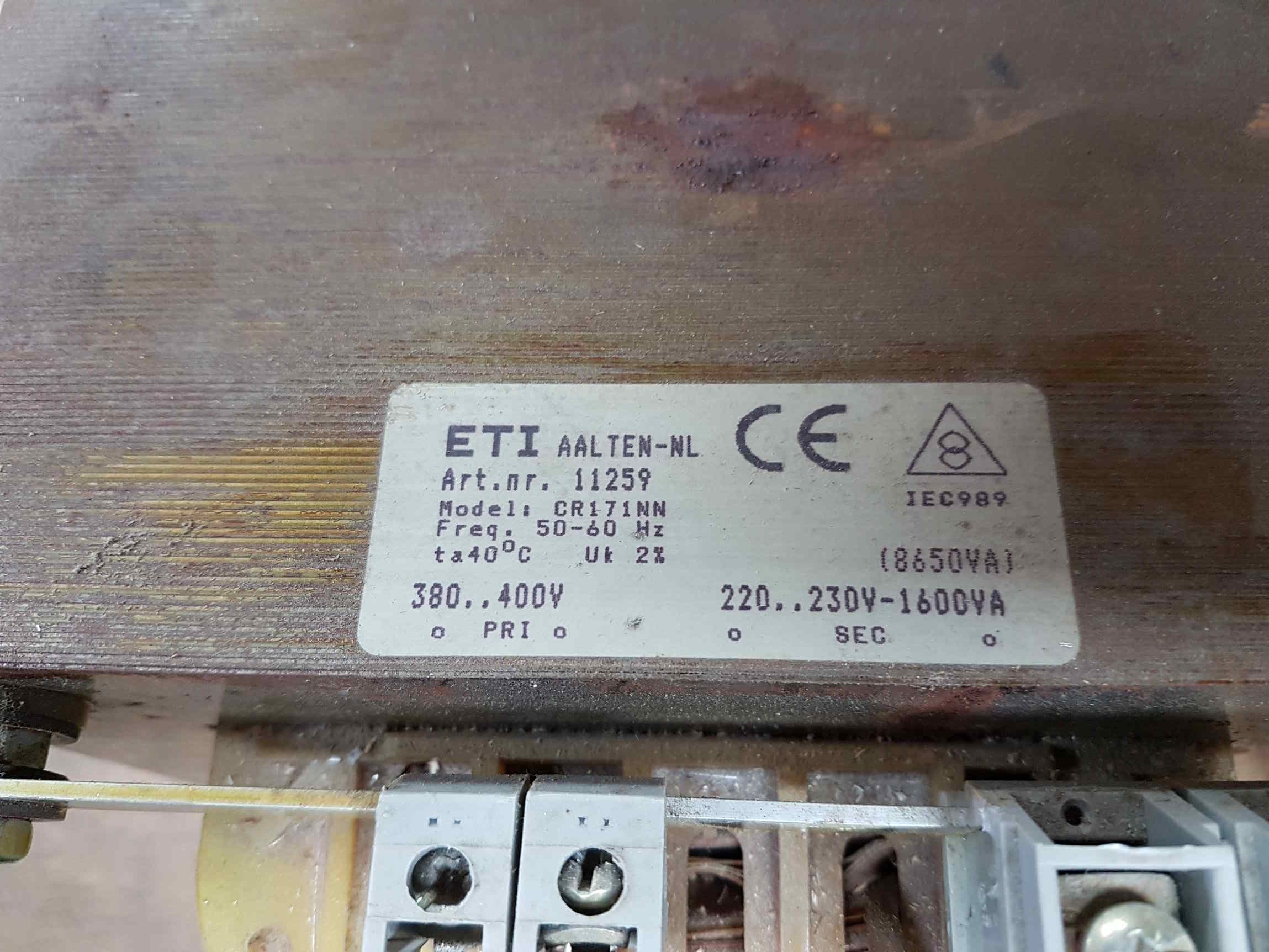
PRICE € 25
